Ages 14 and up • Illustrated handbook
Build robots with V5 Lab
From basic controls to supported shafts, motors, gear ratios and motion diagnosis. Choose a lesson below. Keep this Help tab beside your robot builder while you work.
24 lessons from basics to advanced
Your illustrated learning handbook
1. Build robots with V5 Lab
Learn one small skill at a time. Start by looking around, then connect parts, make them move, and solve harder problems. Keep this handbook beside the app.
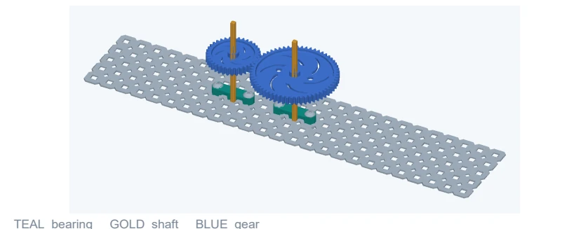
- Open your workbench. Go to v5lab.agcloud.io on a computer. A mouse makes 3D picking easier.
- Follow the learning route. Start with Basics, continue through Connections and Moving mechanisms, then try the Advanced lessons. Use the contents to jump to a lesson.
- Use the pictures. CAD views show real app geometry. Diagrams explain an idea and are not to scale. Control maps are simplified drawings, not screenshots.
Check your result. Each lesson ends with a check. If your result looks different, stop and investigate before adding more parts.
Try this. Designed for ages 14 and up. Work independently or with a mentor. Edition 12 September 2026.
Back to contentsBasics 1
2. Find your way around
You do not need every button yet. First find these four places.
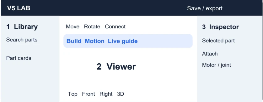
- Find the component library. The left side holds the parts. Use Search parts or part number to find a name or number.
- Find the 3D viewer. The middle is your workbench. Click a part to select it; an outline shows your selection.
- Find the selected-part controls. Look for Attach, Move, Copy and Motor / joint. These describe the part you selected.
- Find the two working modes. Build changes the saved assembly. Motion previews movement. Live guide is beside the Build / Motion buttons.
Check your result. Click one part. Can you find its name in the selected-part panel?
Try this. Point to the library, viewer, inspector and Live guide without clicking anything else.
Back to contentsBasics 2
3. Look around and keep a copy
Make a saved copy before experimenting. Then practise moving only your view.
- Name and save your robot. Use the project name at the top. Open Save / export and choose Save V5 Lab project (.v5lab). Keep the downloaded file somewhere you can find.
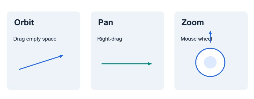
- Orbit the camera. Drag an empty area of the viewer to look around the robot. Avoid dragging a move handle.
- Pan and zoom. Right-drag to pan. Use the mouse wheel to zoom. Try Top, Front, Right and 3D at the bottom of the viewer.
- Practise recovery. Make one small change, then use Undo. Save another copy when you reach a useful checkpoint.
Check your result. The parts stay in the same places when you orbit. Only the viewing direction changes.
Try this. Save a file named My first practice before continuing. Browser saving is useful, but keep your own downloaded copies too.
Back to contentsBasics 3
4. Add and move your first part
Start with one familiar shape, such as a 5x25 Steel Plate. Work in Build mode.
- Add a plate. Search for 5x25 Steel Plate and click its library card. Wait for its model to load.
- Read the selection. Check the name in the selected-part panel. If attachment guidance opens, choose Move to practise positioning.
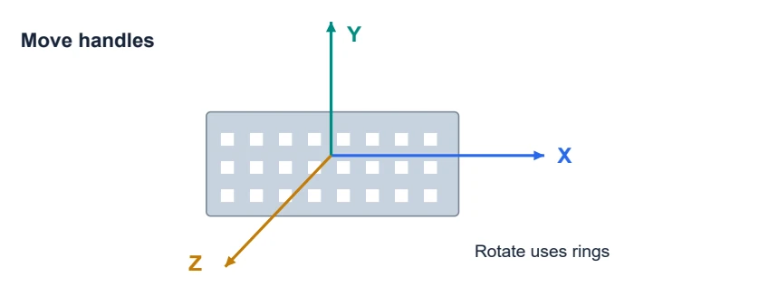
- Move it a little. Choose Move and drag one axis handle. Use a side view to check that you did not accidentally change its height.
- Try rotation. Choose Rotate, turn a ring a small amount, then Undo. Try with Grid snap on.
- Copy and remove. Use Copy to create another part. Select the copy, check its name, and Remove it.
Check your result. You finish with one plate and know how to select, move, rotate and undo.
Try this. Make two plates sit beside one another. They may look close, but they are not connected yet.
Back to contentsBasics 4
5. Know what each part does
Before connecting anything, ask what job each part should do.
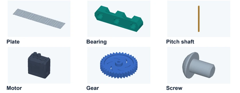
- Structure holds the shape. Plates and channels form the frame and provide mounting holes.
- Bearings support shafts. A bearing housing mounts to the frame. Its bore is the passage for the shaft.
- Shafts carry rotation. For these lessons, choose the regular square pitch shaft. Do not substitute a high-strength shaft; it needs matching parts.
- Wheels and gears use rotation. A wheel can move a robot. Meshing gears transfer rotation between separate shafts.
- Fasteners and retainers matter. Screws and nuts secure mounts. Spacers create separation; collars help keep shaft-mounted parts from sliding sideways.
Check your result. Can you identify a plate, bearing, shaft, gear, motor and screw in the picture?
Try this. Explain why a bearing and a gear should not do the same job.
Back to contentsConnections 1
6. Finish your first live guide
Begin with the short motor-to-plate lesson. It teaches a complete mounting stack.
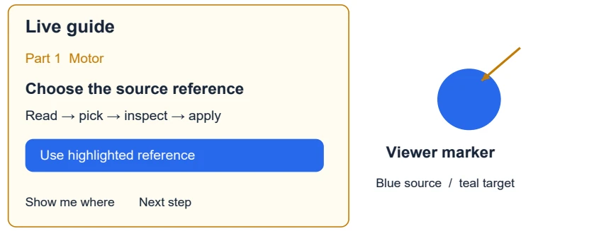
- Open Live guide. Find Live guide beside Build / Motion. Choose Plate → motor → mounting screws, then Start guide. Your previous robot is backed up on this device.
- Get one part. Read the current instruction. Get this part adds one loose component, not a whole finished mechanism.
- Pick the two references. Click the blue lesson marker, then the teal receiving marker when asked. Use highlighted reference is a button alternative to clicking in 3D.
- Choose and inspect. Choose the connection relationship. Preview this connection, orbit to inspect it, then Apply this connection.
- Finish or pause. Use Next step only after the action succeeds. Pause keeps your place. Restore previous robot brings back your backup.
Check your result. You installed the motor and both screws separately.
Try this. Important: Live guide supplies orientation and depth presets. Ordinary Connect asks you to inspect and adjust these yourself.
Back to contentsConnections 2
7. Understand a motor mount
The screw head and the motor are on opposite sides of the plate. The motor housing stays fixed.
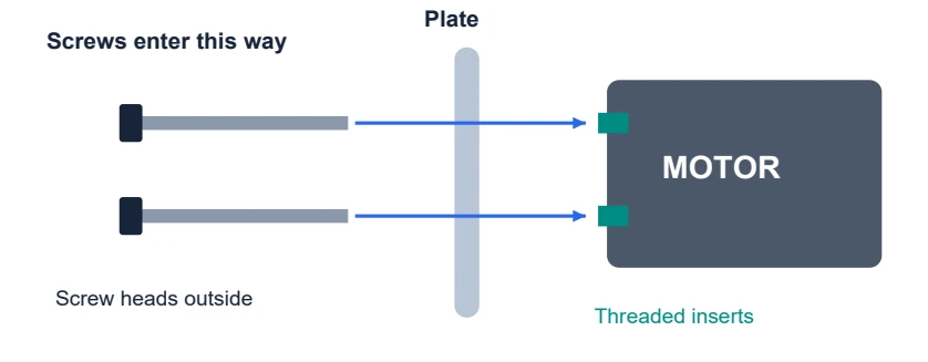
- Find the threaded inserts. Look at the motor face with its mounting inserts. These receive the screws.
- Align the metal holes. The plate holes must line up with those inserts. Check from the other side as well.
- Add each screw. The screw passes through the plate and enters a motor insert. In manual Connect, use the motor insert as the screw destination.
- Inspect the stack. Check the screw head is outside the plate and the screw is long enough to engage the insert. Use the lesson hardware for this practice.
- Separate mounting from driving. A fixed housing is correct. Assigning a motor to a rotating joint is a later step; mounting the housing alone does not make a shaft rotate.
Check your result. Both screws enter from the plate side. Neither screw head is buried inside the plate.
Try this. Repeat the Live guide motor lesson and explain the stack aloud: head, plate, threaded insert.
Back to contentsConnections 3
8. Use Connect yourself
Connect is the toolbar tool. Attach opens the selected part’s connection workflow. Attach parts is the final save action for an ordinary attachment.
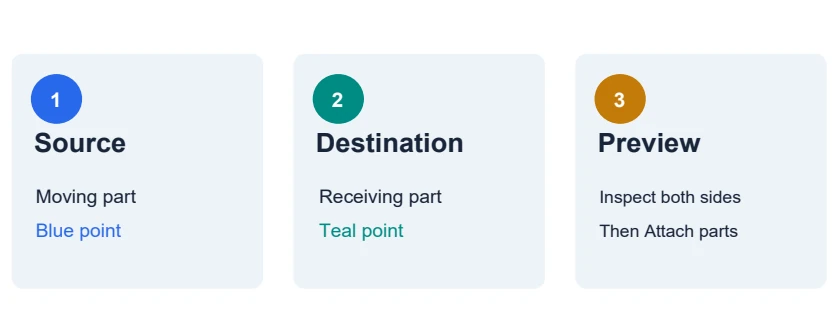
- Choose the moving part. In Build, select the part you want to bring to another part. Click Connect or Attach.
- Choose the source. Pick its blue mounting point. The Attach from list is useful when points are hard to see.
- Choose the destination. Pick a teal point on the receiving part. In Advanced · reference points & alignment, you can instead choose Destination component and Destination point.
- Inspect the preview. Orbit and check both sides. A red preview is blocked. Read the message; adjust the reference, orientation or depth instead of forcing Apply.
- Save the connection. Choose the intended Connection type, then Attach parts when the preview is valid. Open Connections to confirm it was saved.
Check your result. Moving the connected group should preserve the attachment. Mere overlap does not create a saved connection.
Try this. A center reference is not necessarily a mounting hole. Unverified CAD points need a fit and dimension check.
Back to contentsConnections 4
9. Mount a bearing to a plate
Use the Plate → bearings → shafts → gears Live guide for the exact teaching locations.
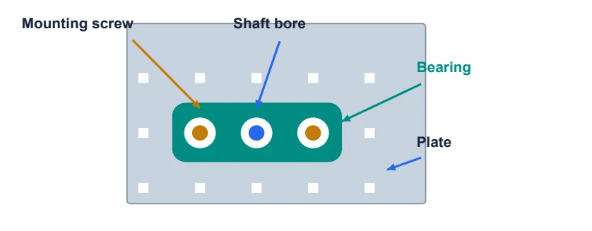
- Start from the plate. Select the support plate in the guide. Get the first bearing when asked.
- Match the mounting location. Choose the source and receiving references. In the preview, check the bearing lies against the metal and its center passage is open.
- Fix the housing. For bearing-to-plate, choose Fixed. The bearing housing must not spin with the gear.
- Install the hardware. Add the two screws and nuts one at a time. Inspect their opposite sides. Do not skip them just because the bearing appears connected.
- Check before adding the shaft. Look through the center bore. The shaft path must continue through a metal hole.
Check your result. The bearing is attached flat, the center path is clear, and both mounting positions have hardware.
Try this. Wrong turn to avoid: choosing shaft rotation for the bearing-to-plate connection.
Back to contentsConnections 5
10. Pass a shaft through a hole
A plate aperture and a bearing bore serve different purposes. Use the regular pitch shaft for this exercise.
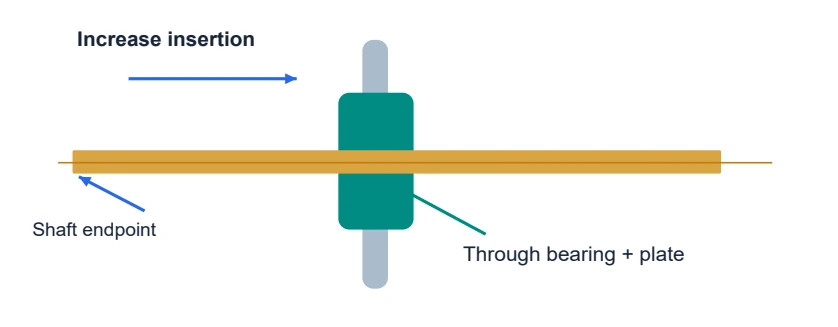
- Learn the plate-only case. Save your work, then load Examples → Shaft through a plate. Inspect its connection: this example keeps the shaft fixed.
- Try manual placement. In Build, select a loose shaft and choose Connect. Choose Pass shaft through hole · midpoint as source, then a compatible plate aperture.
- Choose a specific depth when needed. Use a shaft endpoint source and adjust Shaft insertion depth (mm). Check the preview from a side view.
- Use a bearing for the rotating case. In the bearing lesson, align the shaft through the bearing and plate. Choose Rotating shaft in Live guide, or Turn · hinge or axle for a manual joint.
- Check the moving side. The shaft is the moving side; the bearing and plate are stationary. Do not fix the turning shaft to the plate too.
Check your result. The shaft passes through the opening without the plate cutting across it.
Try this. Change insertion depth in a preview, then Discard. See how the amount of shaft on each side changes.
Back to contentsConnections 6
11. Decide what stays fixed
The same shaft can be fixed to a gear and still rotate inside a bearing.
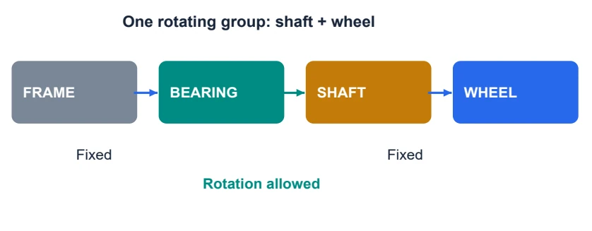
- Frame to bearing. Keep this fixed. The support must stay with the frame.
- Bearing to shaft. Allow shaft rotation. This is the joint that gives the mechanism a way to turn.
- Shaft to gear or wheel. Keep these fixed together for the driven examples. They should turn as one unit.
- Gear to another gear. Use Gear mesh. Each gear still needs its own rotating shaft support.
- Motor housing to frame. Keep it fixed. Motor assignment tells the app which rotating joint it drives.
Check your result. Point to the one relationship that permits rotation in a frame–bearing–shaft–wheel stack.
Try this. Real hardware note: VEX recommends two aligned shaft support points in nearly all assemblies. The small app lessons teach connections; ask a mentor to review support and retention before building a loaded robot. [1]
Back to contentsMoving mechanisms 1
12. Build the powered wheel stack
Use Channel → bearing → shaft → motor → wheel in Live guide. Work through every attachment.
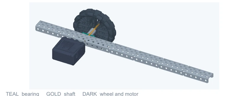
- Build the support first. Mount the bearing and its screws and nuts. Check the shaft passage.
- Insert the shaft. Choose the rotating shaft relationship in the bearing. Inspect its depth before applying.
- Fit the rotating parts. Add the spacers, wheel and retaining parts when asked. Check that the wheel clears the metal.
- Mount the motor. Align and fix the housing, then install the mounting screws. The lesson supplies the fit presets.
- Check the whole stack. Orbit to inspect both ends of the shaft. A collar is for retention; a spacer is for separation. Neither replaces a bearing.
Check your result. The wheel has clearance to turn, the housing is fixed, and the shaft has a rotating support joint.
Try this. Before Motion, point to everything you expect to turn. Keep fingers away from moving parts on real hardware. [1]
Back to contentsMoving mechanisms 2
13. Assign a motor and test slowly
A motor model sitting beside a shaft is not a motor assignment. Set the drive on the correct joint.
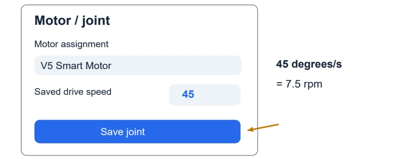
- Select the driven wheel. In Build, select the completed wheel. Click Motor / joint.
- Read the connection. Check that the frame or bearing is the parent and the shaft side can turn. Do not change the housing mount into a rotating joint.
- Assign the installed motor. Choose the V5 Smart Motor in Motor assignment. Enter 45 in Saved drive speed for this lesson.
- Save the setting. Click Save joint. A list selection by itself is not the final save.
- Try Motion. Open Motion, choose the wheel joint if necessary, and click Turn forward. Watch briefly, then Stop.
Check your result. Wheel and shaft turn; the bearing, channel and motor housing stay still.
Try this. Reverse the saved drive direction and save again. Predict which way the wheel will turn before playing.
Back to contentsMoving mechanisms 3
14. Mesh two gears side by side
A gear mesh puts the teeth beside one another. A shaft connection uses the center opening.
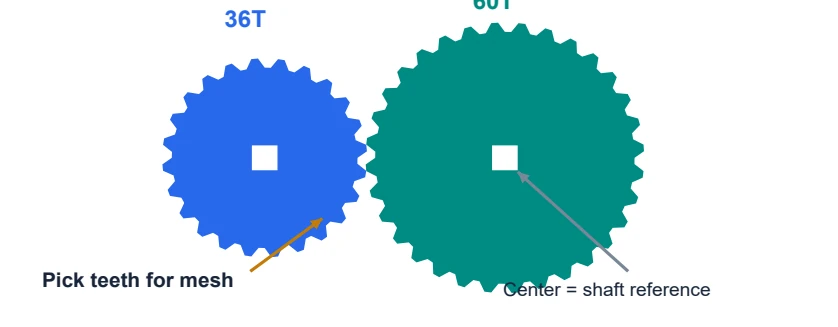
- Choose a pair. Start with two supported gears from the gear lesson, or practise with two loose 36T gears after saving a copy.
- Choose the moving gear. Select it, then Connect. Find the blue ring around its teeth.
- Choose the mesh references. Click the blue ring and the other gear’s teal ring. In the panel, choose Mesh teeth side by side on both gears.
- Inspect the position. Use Position around destination gear (°) if you need a different side. The app sets pitch spacing and tooth alignment.
- Save the mesh. Click Mesh gears when the preview is valid. Check Connections for Gear mesh.
Check your result. The gears sit beside each other instead of sharing one center. A saved mesh is listed.
Try this. Two equal gears turn at equal speed in opposite directions when their shafts can rotate. Mesh alone does not create the rotating supports.
Back to contentsMoving mechanisms 4
15. Build and check a gear train
Complete Plate → bearings → shafts → gears. Do not jump straight to placing the two gear centers.
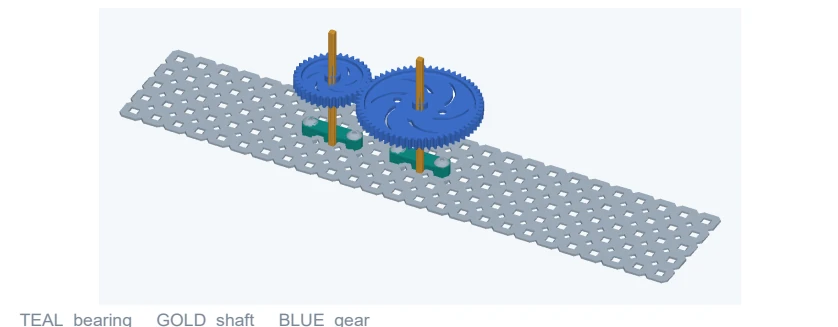
- Install the first support. Mount the first bearing and fasteners. Insert its shaft with a rotating joint.
- Fit the first gear. Fix the 36T gear to that shaft, so it follows the shaft’s rotation.
- Repeat for the other gear. Add the second bearing, fasteners, shaft and 60T gear. Each gear has its own shaft.
- Create the mesh last. Use the mesh relationship. Open Motion, select the first shaft and Turn forward.
- Compare the motion. The 60T gear turns oppositely at 36/60 = 0.6 times the 36T gear’s speed. Stop after observing.
Check your result. Both shafts turn. The bearings and plate stay still. If only one gear turns, inspect the mesh and the second rotary support.
Try this. Load Examples → Three-gear train. Predict the last gear’s direction. Two successive external meshes reverse the direction twice.
Back to contentsAdvanced 1
16. Inspect motion instead of guessing
A mechanism can fit at its starting pose and still hit another part later.
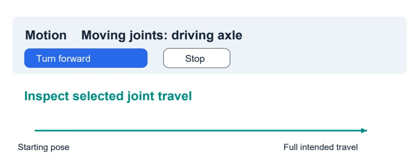
- Choose the intended joint. Enter Motion and read Moving joints. Start with the driving joint, not an unrelated axle.
- Play only that motion. Use the selected-joint preview and Turn forward. Stop as soon as you see an unexpected result.
- Inspect its travel. Use Inspect selected joint travel for a broader check. Read any blocked position and identify the highlighted parts.
- Repair in Build. Return to Build. Fix the mounting reference, joint direction, spacing or obstacle, then preview again.
- Retest from the start. Check the entire intended motion, not just the position that previously failed.
Check your result. No unrelated part moves, and no collision message appears over the travel you intend to use.
Try this. Motion checks sampled geometry. It does not certify strength, motor torque, friction, or the performance of a real robot.
Back to contentsAdvanced engineering 1
17. Calculate a gear ratio
Use tooth counts to predict motion before you press Play. Then compare your prediction with the preview.
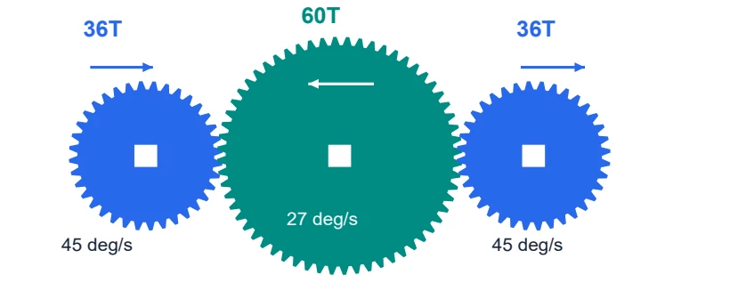
- Count the teeth. Let A be the driver and B be its follower. Follower speed = driver speed × teeth on A / teeth on B, in the opposite direction for an external mesh.
- Work a numerical example. A 36T gear driving a 60T gear at 45 degrees/s gives 45 × 36 / 60 = 27 degrees/s in the opposite direction. Since 360 degrees is one revolution, rpm = degrees/s ÷ 6.
- Extend to three gears. For 36T → 60T → 36T, the ratios multiply: (−36/60) × (−60/36) = +1. The final gear has the first gear’s speed and direction.
- Compare your prediction. Load the two-gear or three-gear example. Select the driving joint in Motion and observe the coupled gears. Do not assign a separate drive to a follower.
- Separate kinematics from force. This predicts relative rotation. The app does not calculate delivered torque, friction losses, or whether a motor can move a real load.
Check your result. For a 60T driver turning at 30 degrees/s and a 36T follower, predict 50 degrees/s in the opposite direction.
Try this. In a design note, record driver tooth count, follower tooth count, input speed, predicted output speed and direction.
Back to contentsAdvanced engineering 2
18. Inspect the rotation axis
A rotary joint needs both the right moving side and the right line to rotate around. Practise on a saved copy.
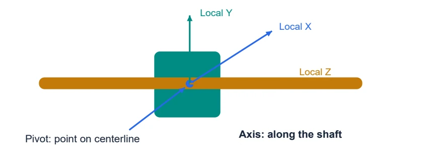
- Open a known example. Load Examples → Bearing + rotating shaft. Select the shaft and open Motor / joint.
- Identify parent and moving side. Read the Parent and Moving side labels. The stationary bearing belongs on the parent side; the shaft belongs on the moving side.
- Inspect the advanced fields. Open Advanced · pivot and axis. Pivot is a point on the shaft centerline in millimeters. Axis is a direction vector along that line; it is not a position or a speed.
- Use a meaningful axis. A vector such as (0, 0, 1) means the parent’s positive local Z direction. Do not enter a zero vector. The correct direction depends on this particular parent’s orientation.
- Choose travel and verify. Use continuous rotation for an unrestricted axle, or appropriate minimum and maximum angles for a limited hinge. Save joint and inspect the displayed axis and motion. Undo experiments that change the intended mechanism.
Check your result. The shaft spins around its own centerline instead of orbiting a point somewhere else. The frame remains stationary.
Try this. Sketch the parent, pivot and axis before editing another joint. A valid number in a field does not guarantee a physically meaningful mechanism.
Back to contentsAdvanced 2
19. Adjust fit with a purpose
Use Advanced · reference points & alignment in Connect after choosing the correct source and destination.
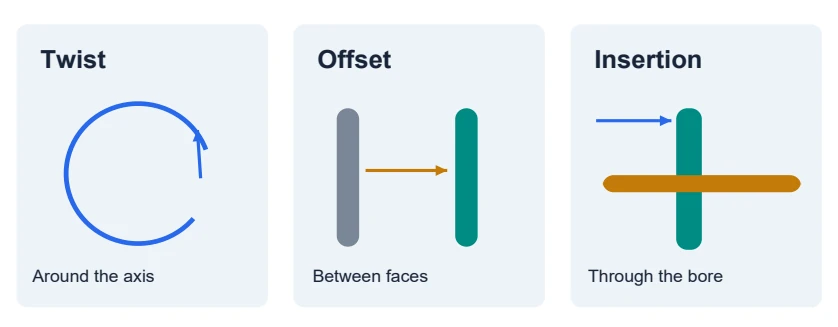
- Twist turns around the connection. Use Twist or Rotate 90° when the holes line up but the part faces the wrong way.
- Flip changes the mating direction. Try Flip mounting direction if the part attaches on the wrong side. Inspect both faces afterward.
- Offset changes separation. Use Offset for a measured gap or spacer position. A floating gap is not a substitute for real supporting hardware.
- Insertion slides a shaft through. For shaft placement, use an endpoint and Shaft insertion depth to control the amount passing through the opening.
- Discard bad experiments. If the preview becomes blocked, read the message and undo the last adjustment. Apply only after the fit makes sense.
Check your result. You can name which control changed orientation, which changed separation, and which changed insertion.
Try this. Change one value, observe, reset, then try another. Keep a note of what each control did.
Back to contentsAdvanced 3
20. Trim a plate in the app
The digital trim tool removes whole rows from supported plates. It is not a physical cutting tutorial.
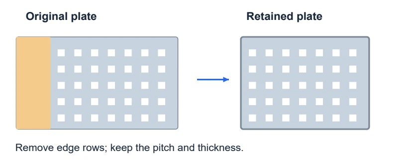
- Start with a copy. Save your build. Practise on a loose 5x25 Steel Plate so existing connections do not complicate the cut.
- Open Cut / trim. Select the plate and find Cut / trim in its controls. It appears only for supported parts.
- Choose the rows. Enter a small count on one edge, such as one row. Left/right use the part’s local X direction; front/back use local Z.
- Preview the retained shape. Click Preview cut. Read the retained size and inspect which holes will remain.
- Apply or discard. Apply cut saves the new shape. Discard keeps the old shape. Undo can restore the previous cut.
Check your result. The holes you need are still present. Thickness and hole spacing have not been stretched.
Try this. If a removed hole is needed by a connection, stop and revise the design. An adult must handle real cutting tools.
Back to contentsAdvanced 4
21. Solve the common problems
Use the exact message in the app as your starting clue.
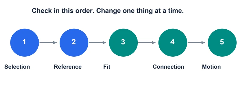
- I cannot see points. Check that you selected a part and opened Connect. Read the banner. If references are hidden, inspect Show unverified CAD points in Advanced; these points still need verification.
- The preview is red. Read which two parts intersect. Check the hole, mating side and insertion depth. Move an obstructing part only if the design allows it.
- The gear will not turn. A mesh needs rotating shaft supports. Check that the shaft was not fixed to the plate and that the correct driving joint is selected.
- The wrong parts turn. Inspect Parent and Moving side in Motor / joint. A motor housing or bearing should usually stay on the stationary side in these lessons.
- The guide will not advance. Complete the requested action and save/apply it. Use Show me where. If you changed the practice build unexpectedly, Pause or Restart; Restore previous robot recovers the backup.
Check your result. After one repair, repeat the test that failed. Do not change five settings at once.
Try this. Select the affected part and ask Assistant to explain its connection or diagnostic. Inspect any suggested change before applying it.
Back to contentsAdvanced 5
22. Save and share your progress
Save a checkpoint after each lesson. Use a different filename for a bigger experiment.
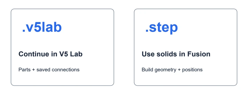
- Save the editable project. Choose Save / export → Save V5 Lab project (.v5lab). This is the file for continuing in V5 Lab.
- Write a useful filename. Try gear-practice-01.v5lab, then gear-practice-02.v5lab after your next successful test.
- Export solids when needed. Choose Export for Autodesk Fusion (.step), then Create STEP file. Wait for completion and use Download STEP.
- Understand what transfers. The export preserves supported solid parts in their saved Build positions, including supported trims. It does not transfer the app’s motion joints or Fusion modelling history.
- Keep both files. Give the STEP to a Fusion user for geometry work. Keep the .v5lab file for the app. If export reports a missing or unsupported part, resolve that message first.
Check your result. You can find your downloaded project file and know which program should open it.
Try this. Add a short design note: what moves, what stays fixed, what you tested, and what still needs checking.
Back to contentsIndependent practice
23. Try three builder challenges
Use the guide when you need it. Then explain the design in your own words.
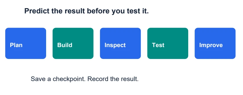
- Challenge 1 The motor mount. Complete the motor-to-plate lesson. Explain why the housing connection is fixed and why screws enter from the other side.
- Challenge 2 The powered wheel. Complete the wheel lesson. Point to the rotating joint, the motor assignment, a spacer and a retainer. Predict the direction before playing.
- Challenge 3 The gear train. Complete the two-gear lesson. Predict which gear is slower. Then inspect the three-gear example and explain the last gear’s direction.
- Record what you learned. Write: My goal was __. I changed __. I expected __. I observed __. My next test is __.
- Ask for a design review. Before copying a digital design into hardware, ask a mentor to check fasteners, shaft supports, retention and clearances.
Check your result. A finished challenge includes a saved file, a successful motion check where relevant, and an explanation of the connections.
Try this. Answers: motor housing fixed; shaft rotates in bearing; 60T follower speed is 60% of a 36T driver; two external meshes make the first and third gears turn the same way.
Back to contentsQuick reference
24. Words and answers to keep nearby
The most useful question is: what should move relative to what?
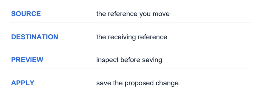
- Source and destination. Source is the part/reference you are bringing to something. Destination is the receiving part/reference.
- Fixed and rotating. Fixed keeps two parts together. A rotating joint lets a moving side turn around an axis relative to its parent.
- Axis and pivot. Axis means the direction of rotation. Pivot means a point on that rotation line. Advanced joint values use the parent part’s local coordinates.
- Preview and Apply. Preview shows a proposed change. Apply saves it. Discard abandons the proposal.
- Mesh and clearance. Gear mesh relates the teeth of two gears. Clearance means space for parts to fit or move without unintended interference.
Check your result. Handbook interface labels were checked against V5 Lab’s editor source and Live guide implementation on 12 September 2026. Screen layouts may vary with size.
Try this. [1] VEX Library, Using V5 Shafts: kb.vex.com/hc/en-us/articles/360035591372-Using-V5-Shafts. More part references: vexrobotics.com/v5-bearings.html and vexrobotics.com/gears.html. App: v5lab.agcloud.io.
Back to contents